Low-voltage systems
Switchboards, power switchgear and the controls between the sources
208 V through 600 V distribution engineered from the fault study up: switchboards, drawout LV power switchgear, automatic transfer switches, main-tie-main and paralleling, metering, control integration, PDC/E-house packaging and modernization of what is already installed.
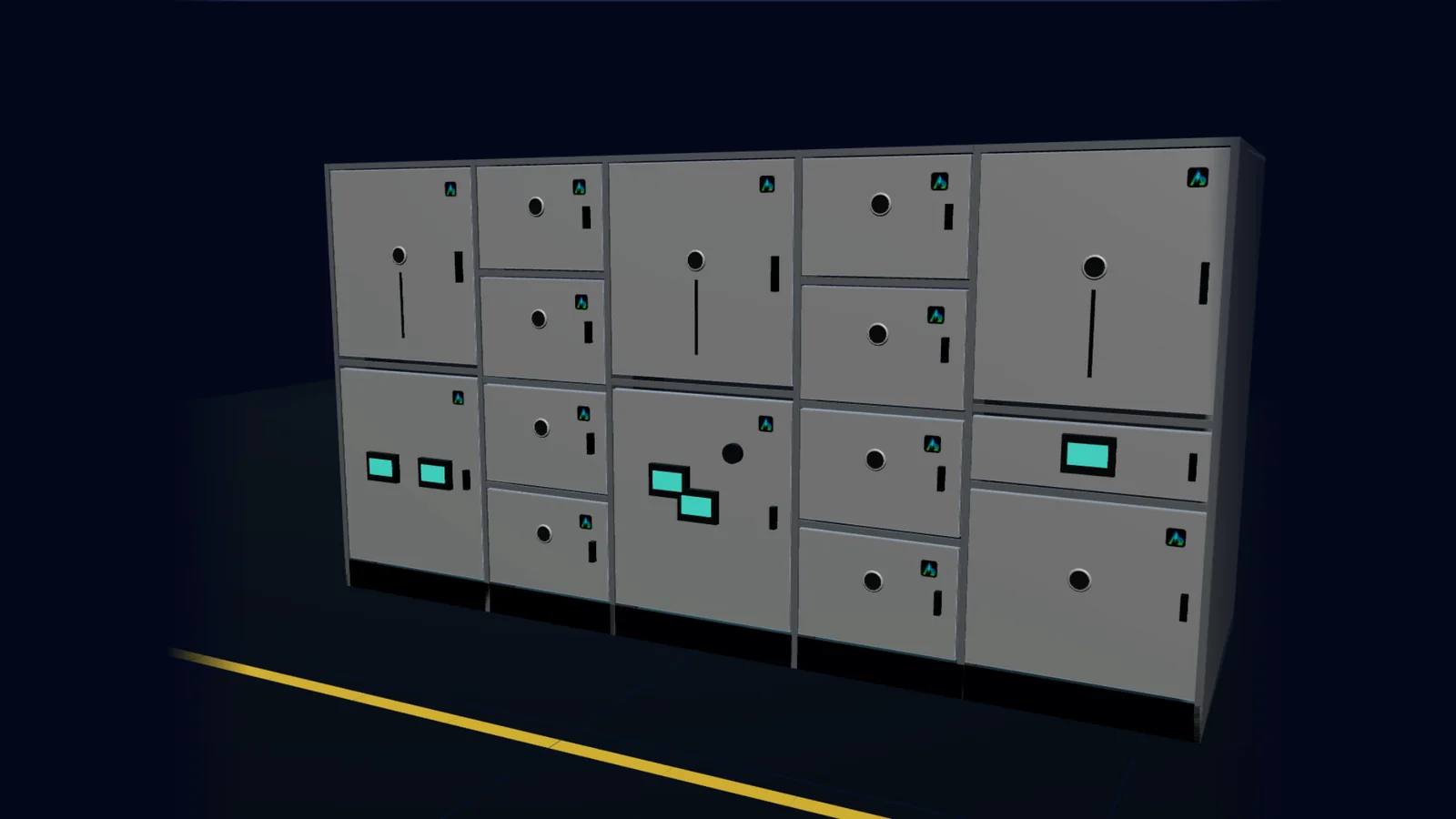
What we engineer and integrate
Low-voltage scope
Each item below is specified against the project's fault study, coordination study and operating requirements — not as a catalog line.
LV Switchboards
Service-entrance and distribution switchboards, 208 V–600 V, with group- or individually-mounted molded-case and insulated-case breakers.
Details +Details −
- · Main-lug, main-breaker and service-entrance configurations with utility CT/pull sections
- · Fixed-mount MCCB/ICCB feeders; drawout ICCB mains where maintainability justifies it
- · Bus bracing and short-circuit ratings matched to the available fault current study
- · Arc energy reduction for devices 1,200 A and larger (ZSI, ERMS, differential or instantaneous methods per NEC 240.87)
- · Metering, surge protection and communications modules integrated at the factory
Typical applications: Commercial buildings, light industrial, tenant distribution, EV charging sites, healthcare normal branch
Switchboard vs. Switchgear: What Actually DiffersUL 891 Switchboards: Scope, Construction and ApplicationNEC Requirements for Switchgear and Switchboards
LV Power Switchgear
Compartmentalized, rear-accessible switchgear with drawout low-voltage power circuit breakers for facilities that cannot afford to shut down for maintenance.
Details +Details −
- · Drawout LVPCBs, 800–5,000 A frames, 100 %-rated, 30-cycle short-time withstand
- · Individual breaker compartments with barriers; CONNECTED/TEST/DISCONNECTED positions
- · Electronic LSIG trip units with zone-selective interlocking and maintenance mode
- · Double-ended (main-tie-main) and multi-source arrangements with automatic transfer controllers
- · Continuous temperature monitoring at stabs and bus joints available as a factory option
Typical applications: Data centers, hospitals (essential systems), process plants, critical infrastructure
UL 1558 Low-Voltage Power Circuit Breaker SwitchgearLow-Voltage Circuit Breaker Types: MCCB, ICCB, LVPCBSwitchboard vs. Switchgear: What Actually Differs
Automatic Transfer Switches
Open-, closed- and delayed-transition transfer switches, bypass-isolation where maintenance without interruption is required.
Details +Details −
- · 100–5,000 A, 2-, 3- and 4-pole, service-entrance rated options
- · Closed transition (make-before-break) where the utility permits brief paralleling
- · Delayed transition for large motor and UPS loads to avoid out-of-phase reclosing
- · Bypass-isolation construction for maintenance without dropping the load
- · Controller integration with generators, BMS and SCADA over Modbus TCP
Typical applications: Emergency and legally required standby systems (NEC 700/701), optional standby (702), healthcare essential electrical systems (517)
Automatic Transfer Switches: Types, Transitions and ApplicationMain-Tie-Main Systems: Design and Automatic Transfer Logic
Main-Tie-Main
Double-ended substations with automatic transfer logic that distinguishes a lost source from a faulted bus — and only closes the tie when it should.
Details +Details −
- · Two-of-three interlocking (electrical and controller logic)
- · Undervoltage sensing (27) with ride-through timers; fault-trip discrimination blocks transfer into a fault
- · Open-transition transfer, or closed-transition with 25 sync-check where permitted
- · Load-shed and transformer FA-rating checks before tie close
- · Auto / Manual / Maintenance modes with SCADA visibility of permissives and timers
Typical applications: Data centers, hospitals, water plants, manufacturing with dual utility feeds or dual transformers
Main-Tie-Main Systems: Design and Automatic Transfer LogicProtective Relaying Fundamentals for Switchgear
Paralleling Switchboards
Generator paralleling and load management for multi-set standby and prime power plants.
Details +Details −
- · Generator breakers with 25 sync-check, 32 reverse power, 40 loss of field, 81 frequency protection
- · First-up/priority-start, load add/shed sequences, soft loading and unloading
- · Utility paralleling and export control where the utility interconnection agreement allows
- · PLC-based or dedicated paralleling controllers with redundant control power
- · Test modes (with and without load) and event recording for compliance testing
Typical applications: Data centers, hospitals, campuses, remote industrial sites, microgrids
Main-Tie-Main Systems: Design and Automatic Transfer LogicSCADA for Power Distribution Systems
Distribution
Downstream distribution sections, panelboard feeds, busway and MCC interfaces designed for selective coordination where the code or the owner requires it.
Details +Details −
- · Feeder schedules built from load studies, not nameplates alone
- · Selective coordination across MCCB/ICCB/LVPCB families
- · Spare and space provisions sized for realistic load growth
Low-Voltage Circuit Breaker Types: MCCB, ICCB, LVPCBNEC Requirements for Switchgear and Switchboards
Metering
Revenue, submetering and Class A power-quality metering integrated into the lineup and the data layer.
Details +Details −
- · Utility metering provisions per the serving utility
- · Tenant and departmental submetering with Modbus TCP or BACnet/IP gateways
- · Power-quality meters with waveform capture and sequence-of-events at mains and critical feeders
Power Quality Fundamentals for Distribution SystemsSCADA for Power Distribution Systems
Control Integration
Transfer controllers, PLC/RTU logic, HMIs and SCADA connections engineered with the switchgear, not bolted on afterward.
Details +Details −
- · Control narratives and I/O lists reviewed with the owner before build
- · Factory acceptance testing of logic with simulated inputs
- · Site acceptance testing with the generators, UPS and utility present
SCADA for Power Distribution SystemsCybersecurity for Digital Switchgear and Power SCADA
PDC / E-House
Power distribution centers and electrical houses: switchgear, MCCs, transformers and controls delivered in a pre-wired, tested enclosure.
Details +Details −
- · Electrical design, equipment integration and testing of the electrical scope
- · Coordination with the building/packaging supplier on HVAC, fire detection and cable entry
- · Hazardous-area siting considerations (purged/pressurized where required)
Typical applications: Oil and gas, utilities, mining, BESS and renewable sites, industrial expansions
Metal-Clad vs. Metal-Enclosed MV SwitchgearArc-Resistant Switchgear: Types, Testing and Limits
Retrofit & Modernization
Extend the life of installed switchboards and switchgear: new trip units, breaker retrofill, relay upgrades, monitoring and controls — often without replacing the structure.
Details +Details −
- · Condition assessment and modernization roadmap
- · Trip-unit and relay replacement; breaker retrofill or replacement
- · Add continuous monitoring, remote operation and SCADA to legacy lineups
- · Phased cutovers planned around the facility's outage windows
What Is Digital Switchgear?Switchgear Condition Monitoring: What to Measure and WhyNFPA 70E, Maintenance and Switchgear Design Choices
Interactive LV equipment
Switchboard vs. low-voltage power switchgear
Toggle between a UL 891 switchboard and UL 1558 drawout switchgear. Open doors, look at the bus, find the trip units and see where sensors sit.
Construction class described by UL 1558 / IEEE C37.20.1; breakers per UL 1066 / IEEE C37.13
Doors closed — as an operator sees it.
Inspector
Select a compartment on the 3D model or a device on the one-line. The model, the one-line and the data panel stay in sync: physical equipment ↔ digital twin ↔ data.
- · Click MV Main 52-M1 on the one-line to highlight its breaker compartment.
- · Click the bus to cut the enclosure away to the main bus compartment.
- · Choose the Sensors mode to see where each sensor physically sits.
Brand-neutral demonstration architecture. Compartment arrangement, ratings and sensor placements are representative of common ANSI practice, not a specific manufacturer's design or a specific Apex project. Values are simulated.
| Switchboard | LV power switchgear | |
|---|---|---|
| Listing / standard | UL 891 | UL 1558 · IEEE C37.20.1 |
| Breakers | Molded-case and insulated-case (UL 489), mostly fixed | Drawout low-voltage power circuit breakers (UL 1066 / IEEE C37.13) |
| Ratings | Devices often 80 %-rated unless specified 100 % | 100 %-rated; 30-cycle short-time withstand |
| Construction | Group-mounted on a common panel; front or front/rear access | Individual compartments with barriers; rear cable access |
| Maintenance | De-energize section to replace a device | Rack out one breaker while the bus stays energized |
| Footprint & cost | Smaller, lower | Larger, higher |
| Where it fits | Commercial, light industrial, tenant distribution | Critical facilities, high available fault current, long service life |
Main-tie-main demonstration
Nine states of a double-ended substation
Step through normal operation, source loss, closed transition, generator pickup, high load, a thermal alarm, a fault trip and maintenance mode. Watch which breakers move — and, more importantly, which ones the controller refuses to move.
Main-tie-main one-line — Normal Utility
- CLOSED
- OPEN
- TRIPPED
- MAINTENANCE
- COMMUNICATION LOST
- Energized
- De-energized
Normal Utility
Both mains closed, tie open. Each transformer carries its own bus; the system is two independent radial feeds with a manual/automatic tie available.
Controller sequence
- Monitors 27 undervoltage on both buses via bus VTs
- Timers (62) armed; AUTO mode selected
- Publishes positions, permissives and timers to SCADA
Interlocks & permissives
Only two of 52-LM1, 52-T and 52-LM2 may be closed (electrical interlock plus controller logic).
Apex Power Distribution · ApexPower.ai
Let's engineer the power system —
and the intelligence around it.
Send a one-line, a specification or a photo of what is installed today. An engineer reviews it and tells you what fits — equipment, protection, controls and monitoring — before anyone talks price.